lab.SCHC
< Lab.SCHC FullSDK Documentation /
On this page:
- FullSDK Concepts
FullSDK Concepts
Preface
Intended audience
This manual is intended for integrators. It presumes that its readers have some familiarity with embedded software development, and with Internet of Things (IoT) domain.
Related documents
You may also find the following documents useful:
- FullSDK Reference Manual
- SCHC: Generic Framework for Static Context Header Compression and Fragmentation
General architecture
Overview
The lab.SCHC FullSDK follows an event-driven and layered-architecture paradigm.
The diagram below depicts the overall architecture of the lab.SCHC FullSDK.
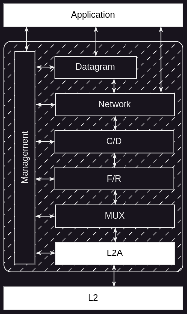
Lab.SCHC FullSDK is the part with a dashed background and implements the layers with a black background. The layers with a white background must be provided by the integrator.
Datagram and Network layers
Network and datagram layers provide the communication interface to the customer application. FullSDK may contain only one of the two layers. The choice is performed at build time.
Datagram layer
The datagram layer provides the communication interface to the application. It provides an API similar to the Berkeley UDP socket API, with functions to create a socket, to send a message and to receive a message.
Network layer
The Network layer provides an API that allows the application to send and receive raw IP packets.
C/D layer
When FullSDK is configured with the datagram layer, the compression/decompression layer applies very little processing: it adds/removes the IP address and the UDP port to/from the packet if the socket configuration requires it.
F/R layer
The fragmentation/reassembly layer is in charge of applying the SCHC fragmentation/reassembly mechanism when required.
The type of fragmentation to be used for downlink sessions and for uplink sessions is defined by a fragmentation profile.
When the above layer requests the F/R layer to send a packet, packet size is compared to the current layer 2 MTU. If the packet size is greater, the message is handed over to the corresponding fragmentation code. Otherwise, it is directly handed over to the MUX layer.
When a packet is received from the layer below, it is provided to the right reassembly code according to the fragmentation type set in the profile, or handed over to the layer above when it is a non fragmented packet. Ultimately, the fragmentation type is preconfigured based on the L2 technology profile.
For downlink ACK-Always and No-ACK fragmentation sessions, the F/R layer provides a polling mechanism.
MUX layer
The multiplexer layer is in charge of serializing the access to the layer 2, when a packet transmission is required. It provides a simple priority mechanism and a one-stage buffer.
When the MUX layer receives a packet, it checks its rule ID. Depending on the rule ID, the packet is handed over to the F/R layer, using the corresponding callback function: the one for processing a packet part of an uplink fragmentation session, or the one for processing a non fragmented packet or a packet part of a downlink fragmentation session.
L2A layer
The Layer 2 Adaptation layer is in charge of providing a standardized interface to the MUX layer, regardless of what the layer 2 might be.
Management layer
The management layer allows the configuration of the different layers. It also maps various FullSDK buffers to the memory block passed by the application layer at initialization time. Additionally, it informs the application layer of specific events:
- Connectivity is available.
- Connectivity is lost (availability depends on layer 2).
- Parameter synchronization is done.
Templates and SCHC Rules
In FullSDK, the concept of Templates refers to the implementation of SCHC Rules for physical devices.
A template is essentially a SCHC compression rule or set of rules that accomodate common values accross devices, while giving the flexibility to set device-specific values. These device-specific values are referred to as template parameters.
For example, the IPv6/UDP stack template defines common SCHC rule fields allowing a device to compress and decompress IPv6/UDP packets, but does not contain information about the IPv6 addresses and UDP ports of the device or the destination application.
It is up to the developer to specify template parameter values.
Dynamic template
By building the embedded application with a dynamic template (build parameter
-DTEMPLATE_ID=dynamic), the developer can set their own SCHC rule template,
through the Management extension
interface.
A binary sequence for a FullSDK template is composed as follows:
- Size (2-bytes): The length of the template itself, in bytes (n-bytes).
- Template (n-bytes): The CBOR sequence representing the template contents.
- CRC (2-bytes): Result of a CRC-16/CCITT-FALSE check on the
size+templatedata content.
Flow control
Flow control can be considered at two levels: for the L2A layer and for the F/R layer. The main principles for flow control are:
- No new message transmission request should be accepted by the L2A layer while one message is already waiting for its transmission.
- No new uplink fragmentation session request is started by the F/R layer while an uplink fragmentation session is in progress.
Consequently, it is up to the application layer to perform buffering, if it requires it. This way, the application has total control on message priority handling, when needed.
Interfaces
Four interfaces have to be considered: management interface, datagram and network interfaces, and layer-two adaptation interface.
Management interface
The management interface is used to configure the lab.SCHC FullSDK at runtime, to provide some hardware resources (memory and timers) that have to be allocated by the execution environment, and to notify the application about information regarding the FullSDK ongoing state.
| Object | Management |
|---|---|
| Processing Power | Whenever the SDK needs to perform processing, it signals it to the application layer that will call a dedicated function. |
| Timers | Resolving a timer must be done in 1 ms. The execution environment must provide a callback that starts the time for n ms, and a callback that stops it. When the timeout is triggered, a dedicated function must be called. |
| Volatile memory (RAM) | Lab.SCHC FullSDK is flexible in terms of memory management. The application must allocate, then provide memory to the SDK. The amount of memory required depends on both the MTU and the maximum payload the application expects to send and receive. |
| Ongoing state | The connectivity state, i.e. whether layer 2 may send or receive data, is signaled to the application layer using a callback. The application layer should not request to send a packet before connectivity is reported as operational. |
Info: All the callbacks are defined when initializing the layers.
Datagram interface
The datagram interface is used to send data packets to a remote application, and to receive data packets from it.
In a way similar to a Berkeley datagram socket, the following operations have to be performed to send a packet:
- Initialize the interface (IPv6/v4).
- Create a socket.
- Bind it to a local port.
- Send a data packet to the remote application, using the socket as a context. The remote application is defined by its IPv6/v4 address and its port.
The send operation is non-blocking and asynchronous:
- It requests a transmission operation and returns immediately.
- The result of the transmission (success or failure) is received later, thanks to a callback declared at interface initialization.
Depending on the packet size and LPWAN technology, a send operation can be
quite long. For instance, if the packet size is larger than the LPWAN maximum
transmission unit (MTU), it will be fragmented and sent in several chunks.
Furthermore, duty cycle limitation may increase the overall transmission time.
Packet reception is also handled by a callback declared at interface
initialization.
In the current version of the lab.SCHC FullSDK, a maximum of three sockets can be created by default. The number of available sockets can be changed at compilation time.
Network interface
The network interface is used to send and receive raw IPv6/UDP data packets to and from a remote application.
The following operations have to be performed to send a packet:
- Initialize interface configure network.
- Information thanks to extension API
- Send a raw IPv6/UDP data packet to the remote application
The send operation is non-blocking and asynchronous:
- It requests a transmission operation and returns immediately
- The result of the transmission (success or failure) is received later, thanks to a callback declared at initialization time
Depending on packet size and LPWAN technology, a send operation can be quite long. For instance, if packet size is larger than the LPWAN’s maximum transmission unit (MTU), it will be fragmented and sent in several chunks. Furthermore, duty cycle limitation may increase overall transmission time.
Packet reception is handled by a callback declared at initialization time.
Layer-two adaptation interface
The L2A layer allows the FullSDK to be independent of the layer two stack.
Since L2A layer does depend on the underlying LPWAN technology, it is usually provided by the integrator. It must comply with a predefined interface which stipulates the following elements:
- A set of callbacks, defined at layer initialization time, that must be called
for the following events:
- the layer requires some processing.
- a packet transmission has been done.
- a packet has been received.
- connectivity is available.
- connectivity is unavailable (may be optional).
- A function that must provide the L2 technology.
l2a_get_technology
- A function that must provide the MTU for the next packet to be sent.
l2a_get_mtu
- A function that must provide the time to wait before a new packet can be sent
(for duty cycle handling).
l2a_get_next_tx_delay
- A function that must request the transmission of a packet. It must be
non-blocking, as the result is provided with the
transmission_resultcallback.l2a_send_data
- A function that performs processing. It will be called after the callback
signals that the layer requires some processing.
l2a_process
- A function that must provide the device IID. Can return false if not
implemented. This function is mandatory only to be compliant with
RFC9011.
l2a_get_dev_iid
The transmission_result callback signalling the end of a packet transmission
must be called only when the communication module / board can switch again to
transmission mode (without taking into account possible duty cycle
restrictions).
The function that provides the time to wait before a new packet can be sent will be called by the FullSDK as soon as the end of packet transmission has been signaled.
The current version of the lab.SCHC FullSDK provides a reference implementation of the L2A layer for the ST NUCLEO-L476RG microcontroller board and the SX1276MB1MAS LoRaWAN shield using Semtech LoRaMac-Node stack.
How to use the lab.SCHC FullSDK
This section describes the logic of initializing, configuring, and using the lab.SCHC FullSDK in different scenarios.
Role
The role of lab.SCHC FullSDK is to enable the SCHC compression and fragmentation mechanisms on device side, either by being fully embedded into an AT modem application that receives messages from an UDP client, or by being deployed on the device directly.
Layer integration
Lab.SCHC FullSDK integrates with both the underlying LPWAN technology and the upper application layer.
The configuration of lab.SCHC FullSDK at runtime, the exchange of packets or the adaptation with the Level2 layer are tasks assumed by interfaces, each provided in a dedicated header file.
Paradigm
One major structuring requirement for the lab.SCHC FullSDK is the ability to support low power modes. Consequently, its implementation allows it to be fully integrated in an event-driven environment.
- When an event concerning the lab.SCHC FullSDK occurs (e.g. data reception, timeout, etc.), the application layer is informed by a callback.
- Then, the application decides whether to let the Acklio FullSDK process the event or not. If yes, it calls a dedicated function.
- Once an event has been processed (the dedicated function has returned), the lab.SCHC FullSDK does not perform any additional processing.
Sequence diagrams
The following sequence diagrams present some use cases.
Interface initialization and configuration
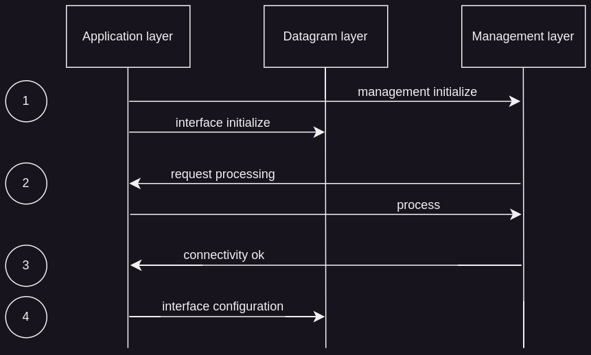
The above diagram presents the successive function calls that must be performed by the application layer to initialize and configure the interface that will be used, and resulting callbacks that will be called by the lab.SCHC FullSDK for related events.
In step 1, the application initializes the management layer and related interface. See the reference manual for details on the initialization of the datagram interface.
As soon as the management layer has been initialized, the callback signaling that the FullSDK needs some processing may be called. In response to this callback, the application layer must call the management layer function that will perform this processing. Step 2 presents one such dialog for this use case. More may occur.
The callback requesting processing is called in an interruption context. The processing function must not be called from this callback, as its execution may take some time. Consequently, the application layer has to decouple the call to the processing function from the activation of the callback. See the reference manual for more information.
In step 3, the SDK signals that the LPWAN connectivity is available. For instance, for a LoRaWAN network, this means that the Join procedure has been successfully performed.
The application layer has to wait for connectivity before interacting with an interface. In step 4, the interface is configured. See the reference manual for the configuration of the datagram interface.
Packet transmission with fragmentation
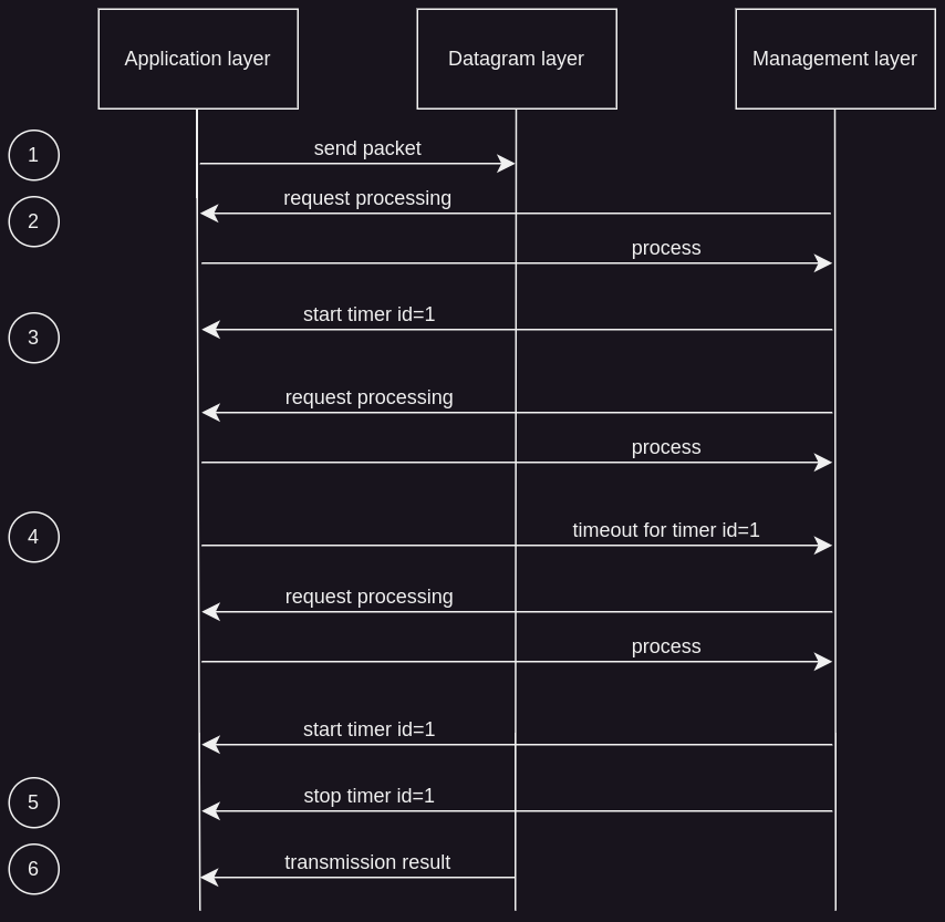
The above diagram presents the calls for the transmission of a packet involving SCHC fragmentation.
In step 1, the application layer requests the transmission of a packet.
In step 2, the lab.SCHC FullSDK signals that it needs some processing and the application layer calls the associated processing function. This interaction will happen several times.
The fragmentation procedure requires some timers. In step 3, the FullSDK signals that the execution environment must start a timer with id=1. This timer must have been created by the application layer beforehand. The timer duration is provided by a parameter of the callback. The timer must have been associated with the SDK function that must be called when the timer expires (timeout event).
In step 4, the timeout occurs. The timeout function associated with the timer must call the corresponding SDK timeout function, as explained above.
The timeout function may be called in an interrupt context. Later on, the timer must be started again.
In step 5, the SDK requires to stop timer id=1.
In step 6, the result of the transmission is returned. In this use case, if this result is positive, this means that the fragmentation process went well and that the packet has been transmitted successfully.
Packet reception without fragmentation
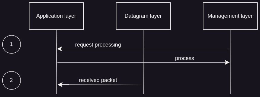
The diagram above presents the calls for the reception of a packet, without SCHC fragmentation.
In step 1, there is the usual request for processing. Again, even if it is presented only once on the diagram, it may occur several times.
In step 2, the application layer is provided with the received packet. The callback should save the received data to a safe place and should then return as soon as possible.
If fragmentation had been active, the timer functions would have been called as it is shown in the previous section.
L2A layer initialization and transmission handling
The following sequence diagram presents the initialization of the L2A layer:
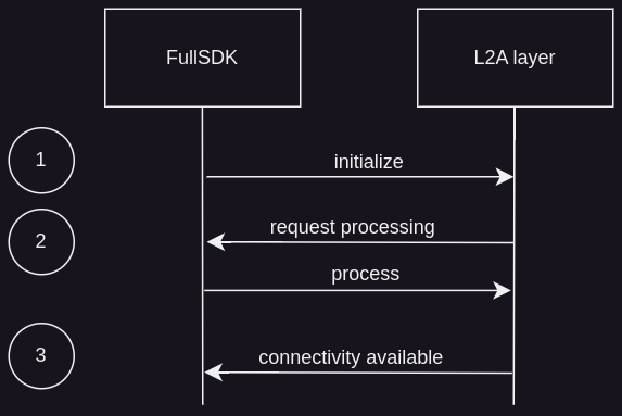
In step 1, the FullSDK calls the initialization function.
In step 2, the L2A layer signals to the FullSDK that it needs to perform some processing. In response to this request, the SDK calls the function performing processing. The L2A layer may perform the number of calls of the callback requesting processing it requires.
In step 3, the L2A layer signals that connectivity is available. For instance, for a LoRaWAN layer two, this means that the Join procedure was successful. The FullSDK will not try to use L2A layer for transmission or reception as long as the callback informing about connectivity availability has not been called.
The following sequence diagram presents the handling of a transmission request:
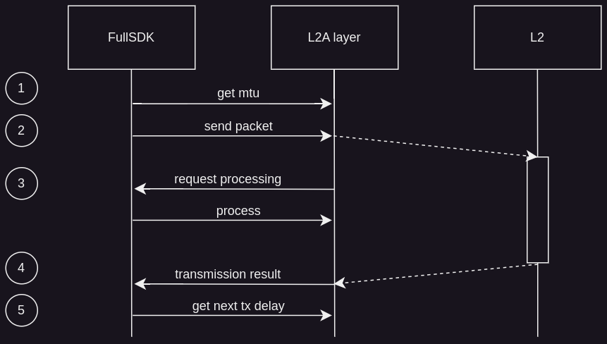
In step 1, the FullSDK asks for the MTU that will be used in the next transmission. This request allows the SDK to support L2 technologies with variable MTU (e.g. LoRaWAN).
In step 2, the FullSDK requests the packet transmission. Soon afterward, the layer two will start transmitting the packet.
In step 3, when required, the L2A layer performs the usual request for processing. Even if it is presented only once on the diagram, it may occur several times.
In step 4, the layer two is back to idle state, ready to transmit again, unless there are duty cycle restrictions. L2A has to signal this event to the lab.SCHC FullSDK by calling the transmission result callback.
In step 5, the lab.SCHC FullSDK requests the time that it has to wait before requesting a new transmission. This request allows the FullSDK to support L2 technologies with duty cycle restrictions.
Bare metal projects
In a bare metal project, where lowering power consumption is important, the application architecture is usually similar to this one, based on a main loop:
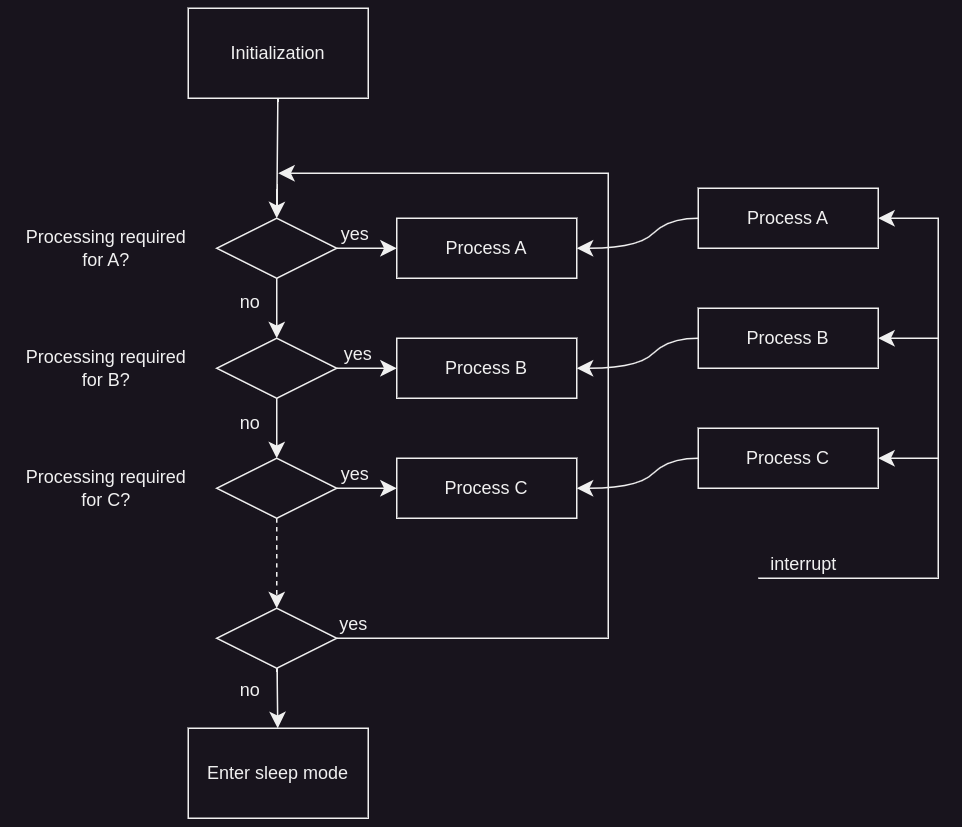
After initialization, the main loop usually enters sleep mode. It exits from sleep mode when an interrupt occurs. Each interrupt service routine signals to the main loop that an event occured, and that some processing is required. It is then up to the main loop to call the function that performs such processing. Once required processing has been done, the main loop enters sleep mode again. The Acklio FullSDK can easily be integrated in such an architecture. The callback called by the Acklio FullSDK to signal that some processing has to be done can set a flag. This flag is checked by the main loop every time it has exited sleep mode. If the flag is set, the main loop calls the associated processing function.
RTOS projects
In an RTOS project, the developer can rely on the various features provided by the RTOS: threads, semaphores, etc.
In such a project, the lab.SCHC SDK would run in one thread. This thread would wait on a semaphore (for instance). The implementation of the callback requesting processing would give the semaphore.